 |
| ||||||
Battery MonitoringA battery is dependent on all of its cells. The only way of controlling each cell in a battery is to have a battery monitoring system that continuously measures total current and individual cell voltage. In any in case of a deviation greater than a certain value the battery monitoring system should send an alarm signal. With such a system any failing cell can be identified at an early stage and by replacing that individual cell further damage is avoided. This method will guarantee the battery’s health through its whole life cycle.
Discharging battery cells connected in series.When discharged a battery must continuously generate a certain amount of current and voltage in order for supported equipment such as an UPS to work properly. A battery's terminal voltage is the sum of the cell's unloaded voltage, EMF, minus its inner- and connecting lines' resistance multiplied by the current. Therefore, terminal voltage drops as a result of an increased current. A defect cell usually has higher internal resistance resulting in lower terminal voltage than other cells in the same battery. At high load current it is fairly easy to detect a defect cell by measuring voltage on each cell or block of cells. However, this requires that each cell's voltage is measured simultaneously. With a battery monitoring system that stores measurement values and compares new values with historical data very small variations in a cell's internal resistance can be identified well before the cell is ruined.
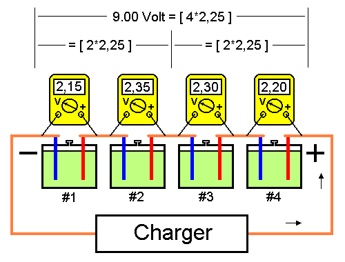
Charging battery cells connected in series.A battery containing a number of cells connected in series is recharged using a voltage recommended by the manufacturer multiplied with the number of connected cells. Fig.1 below shows a battery with 4 cells charged with 2.25 per cell, a total of 9 volt. Total voltage and average cell voltage is generated by the charger. However no cell has recommended recharge voltage of 2.25 volt. Therefore, the battery manufacturer has stated the maximum amount a cell's voltage is allowed to deviate from the average. This value is usually +-0.10V which in this case means that each cell's voltage must be between 2.15 and 2.35 volt.
Fig1. Battery with normal cell voltage.
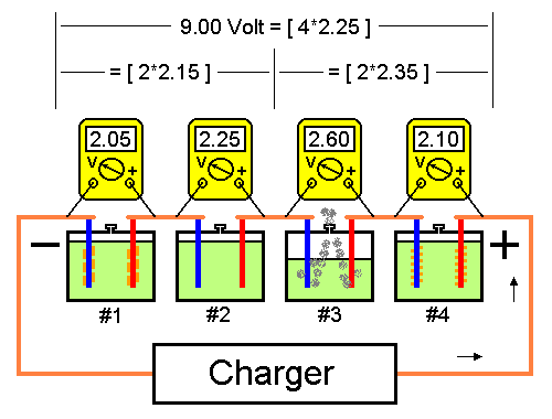
Fig.2 below shows the same battery with a defect in cell #3 resulting in an increased internal resistance. An increased internal resistance results in an increased cell voltage, in this case 0.3 volt. This means that the other cells' voltage drops with 0.1 volt. The water in Cell #3 is transformed into explosive hydrogen gas. In case this problem is not discovered also cell #1 and cell #4 will fail as a result of low charging voltage. Furthermore, low charging voltage will result in the formation of highly insoluble lead. The water in cell #3 is transformed into explosive hydrogen gas. In case this problem is not discovered, cell #1 and cell #4 will also fail as a result of low charging voltage. Furthermore, low charging voltage will result in the formation of highly insoluble lead sulphate on the cell plates. Cell #2 will stay unaffected until all water in cell #3 is consumed.
Fig2. An increased cell voltage results in decreased voltage over remaining cells.
In this particular case a Battery Monitoring System would trigger an alarm as soon as voltage over cell #3 exceeds 2.35 Volt. During maintenance charging it is difficult to discover individual failing cells when reviewing data from more than one cell per channel. If the cells in Fig. 2 are grouped in pairs, average voltage in group 1 (cells #1 and #2) is 2.15 Volt and in group 2 (cells #3 and #4) 2.35 Volt. Both these values are within limit.
Conclusion
|
||||||||||||||

