 |
| ||||||
Batscan in Electro Refinery plantsIn an electro refinery plant metals are purified by electrolysis. The process involves a metal having low purity that are anodes in an electrolytic cell in which the same metal but with a higher purity builds up at the cathodes when an electric current flows through the cell. When refining copper, both electrodes are made of copper and the electrolyte is water, sulfuric acid and copper sulfate. Each cell contains between 40 and 80 pairs of electrodes where each electrode has a surface area of about 2m2. Typically 200 to 400 cells are connected in series and connected to a rectifier powered from the main grid. The voltage across each cell is approximately 0.35V. The current through the cells is adjusted to about 30mA/cm2. With 43 cathodes in a cell, the total current is about 26 000A. The absolute voltage over the individual cells varies from about 300mV at the beginning of the process to about 400mV at the end when the distance between the electrodes is the greatest. The difference between the voltages across the various cells is very small and ideally within a few mV during the entire process. |
|
|
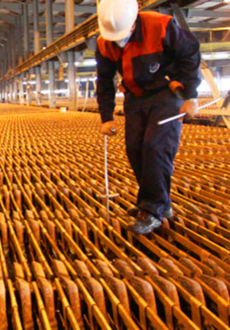
Tank house workContinuous monitoring and adjustment of the electrodes is essential for maximum production yield. 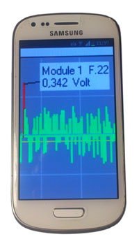
The relative balance between the cell voltages are monitored by Batscan with high accuracy. An aberrant cell voltage indicates that the process does not function optimally. A handheld terminal makes it easy to quickly locate abnormal cells and provides immediate feedback to the operator of the results from the corrections made on the cell. A very low cell voltage it usually an indication of a short circuit between two electrodes. An only slightly increased cell voltage may indicate a faulty connection to one electrode, or so called anode passivation. |
|
|

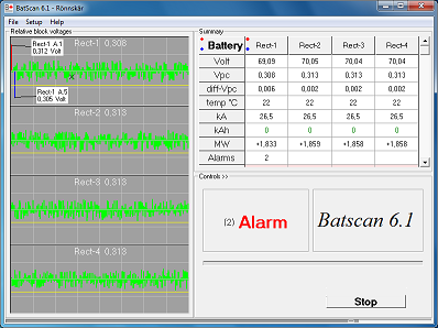
The Batscan softwareThe measuring modules are controlled from the Batscan program. All cell voltages are measured in cycles that repeats every 5 seconds, shown in a progress bar in the main window. A measurement cycle starts with all channels being measured synchronously, simultaneous sampling, 250 times during 500ms. Then the modules are polled in sequence for the digitally filtered measurement values from all channels which is displayed both graphically and numerically in the main window. All changed values are saved on the hard drive for later analysis. Readings outside the alarm limits triggers an alarm. By pointing to a bar in the graph, the cell number and voltage are shown. |
|
|
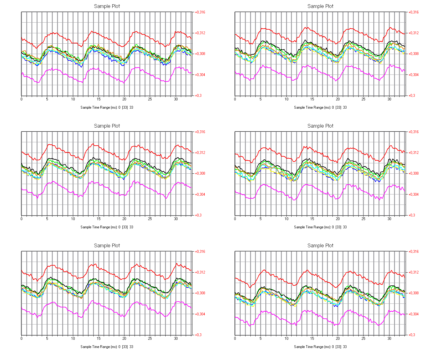
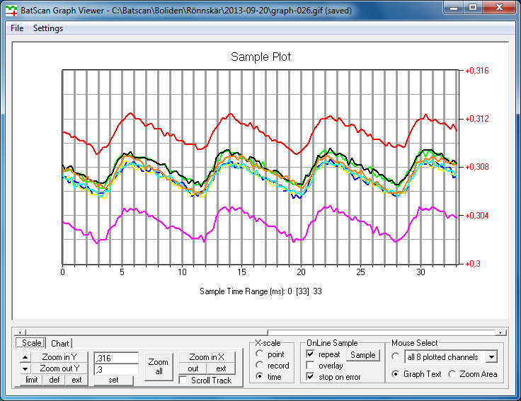
Advanced AnalysisThe filtered measurements shown in the main window is the average voltage, DC, without AC component. For a more detailed analysis it is also possible to see the actual waveform, as in an oscilloscope, in real time. Here you can also see the ripple from the rectifier and small variations in the DC level coming from the mains. Normally, all the curves lie in each other. In this example, cell 1 and 5 of the bank is aberrant. One electrode in Cell 1 is not in contact with the intercell bus bar rail. Cell 5, with its 3mV lower voltage than the others, it is more difficult to diagnose because of a "normal" shorting typically yields much lower DC level and ripple. Here, instead one can suspect lower resistance due to elevated temperature which in turn may be due to poor circulation of the electrolyte. |
|
|
Installation of measuring modulesThe corrosive environment in a refinery plant places high demands on the equipment installed there. Batscans modular design makes it possible to customize the installation after the specific requirements. |
|
|
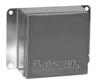
1-2 channel measurement module (with temp) in stainless steel or GRP enclosureThis enclosure is suitable for a measuring module that must be placed at each or every other cell tank, which is required when cell temperature must be monitored. For wireless data transfer with internal antenna and power supply from the monitored cell, GRP (Glass fiber Reinforced Polyester) is used, otherwise stainless steel may be used. |
|
|
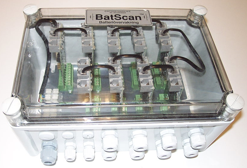
Multi-channel unit (without temp) in polycarbonate or GRP enclosureIn this housing all the BA683 cell voltage modules required to monitor all cells in a cell group can be fitted. A measuring wire from each power rail (at the edge of the cells) is connected to the unit. Communication with the Batscan computer can be wired or via radio link. |
|
|
Connecting to the Batscan PC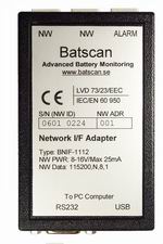
BNIF-USBConnects Batscan RS-485 bus network directly to a USB port on the Batscan PC. This provides the fastest communication link without delay and is preferred if direct cable connection is possible.

WiFi infrastructureLinks the Batscan communication over existing or separate wireless network. |
|
|